Navigate:
Project Owner: Robert
The project all came about when work was clearing out an old warehouse full of junk and into the scrap pile went a 10kW PMSM motor. Of course this was too much to let go by so we salvaged the motor to begin working an EV conversion.
As an electrical engineer I'm taking the difficult route of designing and building every electrical component myself. These include the following
- Three phase controller for motor.
- Battery management system
- Battery charger
- 1kW DC/DC converter for onboard accessories
- Fancy cabin controls and dials.
The car I've gone with is a Toyota MR2 as it has low drag, has electro-hydraulic power steering and provides plenty of room for batteries.
Motor controller
The motor controller is a three-phase vector controller. The IGBT stack is built from discrete Semikron Dual Pack modules and controlled by a TI C2000 DSP + FPGA controller. I spent a lot of effort writing code to allow the controller to be developed in Matlab Simulink which then generates c code of the controller which is downloaded to the DSP. This allows me to work on the controller and simulate it where ever I am with my laptop.
The motor is a 10kW continuous perm mag synchronous machine (similar to `brushless DC' but with no cogging etc) designed for use in servo applications. It has a 7 times over current rating! The motor is shown here:
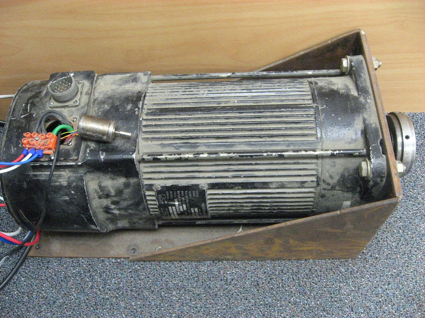
The adapter plate between the motor and the gearbox and being built at present and are due to be here next week (mid Sept 2010). I'm really looking forward to seeing the gearbox drive shafts spinning!
Batteries and BMS
I ordered 120 40Ah Thundersky LFP cells to produce a ~400 volt nominal pack voltage (320v min and 510v fully charged). The relatively high pack voltage has many advantages, the primary one being the low current cabling required. There are also charging benefits from having a high pack voltage detailed in the charger section.
The BMS has been the most time consuming and expensive part of the whole project to date. But it's incredibly rewarding now that I've finished the 20 balance boards (each one does 6 cells), the controller board with 10 LTC6802 devices and the aux micro for controlling the whole lot. The micro now periodically measures all the cell voltages and I've written a crude BMS module to perform balancing when charging. I've got a nice tech-app (c# on the PC) that can read all 120 of cell voltages from the aux controller and turn on/off the balance resistors. And just for fun I wrote a quick sequencer that flashes all the balance resistor LEDs. You can see them flashing at:
The auxiliary controller the controls the BMS has a few additional features built in, including earth leakage detection to ensure the battery pack is perfectly isolated. It also provides control for the DC/DC converter and other auxiliary controls in the car.
I've just finished boxing the BMS controller up in a nice box and made up fancy cables for it etc.
Charger
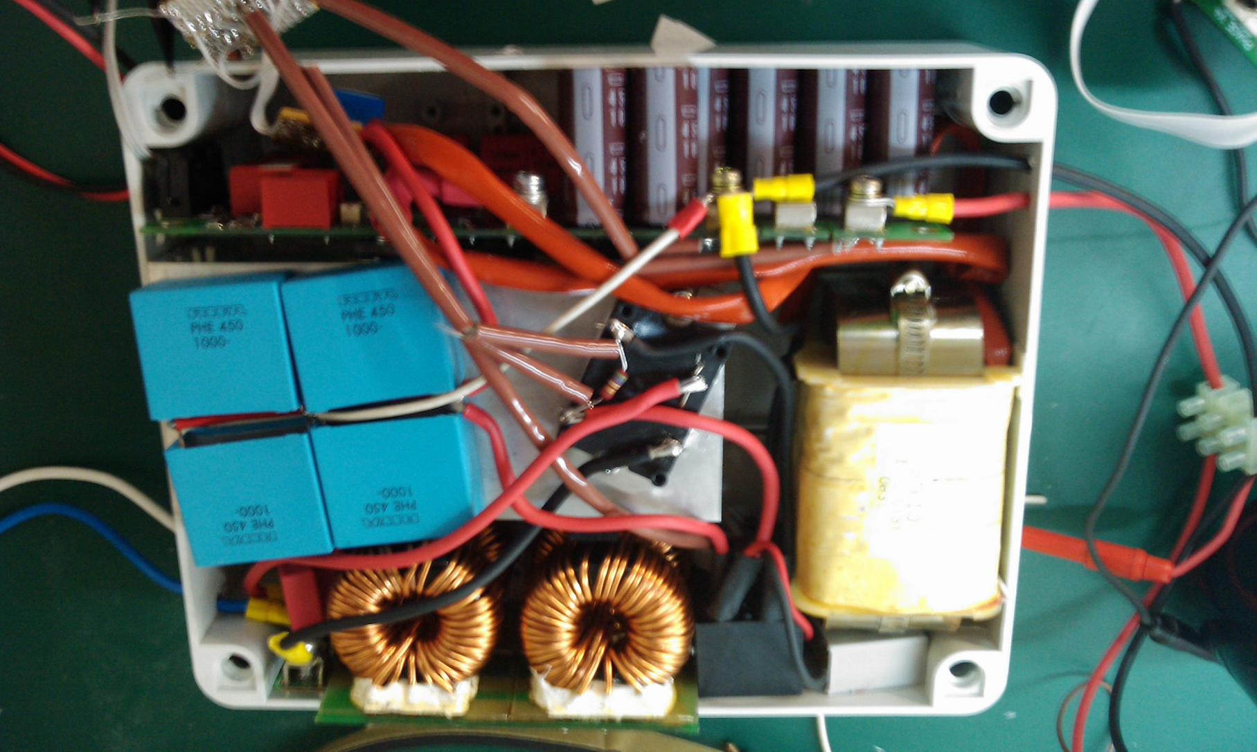
One advantage of having a high battery voltage is that the charger can be a simple boost converter design. As such I've built an 8kW unity power factor (PFC) charger. The charger gets its control from an additional PWM signal on the motor controller DSP. This allows the charger to fully operate while the motor is running for use with a range extender generator. The charge control (cascaded voltage and current controller) are again implemented in Simulink. It's been fully tested up to 8kW from a high current single phase supply. The recently boxed charger is shown here:
1kW DC/DC converter
One disadvantage of using a high pack voltage is that I couldn't use an off the shelf step down power supply for the in-car 13V supply. The supply needs to be able to support all regular 12v functions including the MR2 electro-hydraulic power steering. To build the converter I heavily modified an isolated resonant converter design we use at work, and after winding an appropriate transformer and creating a synchronous rectifier I have a 1kW 13V supply. It also has a low power (~10W) always-on supply which powers the relevant controllers when the car is off (ie doors locked and not charging). My next task after boxing the charger is to box the DC/DC converter.
Fancy dials
The in-car controls have been through several iterations. Both the motor control DSP and the auxiliary controller talk a custom high-speed low latency protocol I've written for reading/writing paramaters and variables (and providing firmware updates) to and from the in-car controls. Progress was as follows:
One of the key points to mention before people wonder "what's with his Microsoft .NET fascination, why not Linux" is that I'm willing to spend a tiny bit more to cut development times down (I'm referring to a 'bit more' as possible code inefficiencies in .NET). By using techs like .NET I can turn out results incredibly quickly (no point in further arguing this here, anyone from Linux who's not convinced: beat .NET WPF and I'll listen). The other advantage of .NET is that I have been able to write drivers that work on the different hardware as they all use the same language (drivers such as the high speed + robust comms between the computers and the main motor controller). So here's what I evolved, what I'm planning on eventually ending up with and where it is at now:
The original plan was to
1) Have a small PC with a 7" screen as the center-console entertainment center but also able to display slow changing but content-rich car details ie charge levels/balancing of individual battery cells, much like what they have in other commercial EVs (hybrids) like Tesla, Prius* etc. The computer would also provide firmware and parameter management for the different onboard computers (motor controller, aux controller, guage computer). The key theme with the PC is that it is not required to be operational to allow the car to run (due to obvious hardware+OS reliability issues). As I was getting other pcbs made for the car I drew up an ATX PSU that could run from 8v to 20v (aux 12v supply) and used the in-car 5v standby power. More details to come in section 2c...
2a) Use a dedicated micro with a TFT lcd with high speed comms to the main controller for gauges. I originally started with a 72MHz ARM7 with TFT display running .NET Micro (GHI Electronics - Embedded Master). I bought the controller and LCD and began drawing dials etc but quickly found that the advantage of using .NET Micro was short lived due to the lack of graphics APIs (some of the documented routines such as drawing circles etc only partly work and it's been confirmed). Not to mention I wasn't even going to get close to the fancy alpha-blended and layered controls I was hoping for.
2b) Given the limitations of the .NET Micro system I then thought of using a Windows Mobile PDA as I knew it had a rich subset of the Win32 APIs and I had done extensive programming in Windows Mobile before (SourceForge MAPIdotnet). This was looking really promising. I got a power 520MHz WinMob PDA (broken touchpanel input = perfect, don't have user feedback) and starting looking at how to lever the *hidden* GDI+ libraries that are actually in WinMob but they aren't exposed. After weeks of sweat and tears and effectively having to rewrite how layered controls in a Form are drawn so that I could get fancy transparent layered controls (where if the background control redrew it would redraw the layered foreground control would redraw too) I finally had something usable. It was fast and looked *ok* but I wasn't happy. I was back at having to apply a lot of effort to get what I wanted. It then occurred to me that I was trying to do all these things that a PC can do without even blinking an eyelid. Even if I did write everything I wanted, the PDA screen was only so big (4" I think) and would eventually run out of processing power too.
2c) Introduce Intel's dual core Atom proc + Nvidia's Ion chipset. For screens was now looking at at least twin 7" LCDs (one for guages, other for center console). I got hold of a 7" LVDS panel + VGA to LVDS board for a pretty penny. I later built a DVI to LVDS converter (more info on this at the bottom). My first Atom board was on the Intel ones which only had a single VGA connector (all before Nvidia released Ion). But I wanted at least dual 7" LCDs and don't you just hate the idea of going from a digital source to analog (VGA) then back again? I got hold of a dual DVI head PCI vid card (Quadro NVS 280) which worked (right on the limit of my homemade PSU). So it all worked but then along came Nvidia's ION didn't it? Thankfully I was able to sell the Intel board to a mate and before I bought a Zotac IONITX-D (DVI+HDMI+VGA outputs) I confirmed on another mate's that the DVI and HDMI could operate concurrently with two of my DIY DVI->LVDS converters + 7" LCDs. This all fit in beautifully with my desire for advanced gauge graphics (using .NET WPF which heavily leverages off DirectX). The worse thing that can happen is that if the PC goes down (insert Windows jokes here...) there'll be no dials to show power usage, battery level, regen etc on the trip home.
Graphical layout (code)
With a single computer for the center console and gauges I've started looking at how to do the graphics. From the start I've had this dream of drawing a couple of gauges etc (and a 7-segment display to show what gear I'm in like Ferraris) and being able to have a notification box popup in the middle (to show important messages - seatbelt?) but be semi-opaque so that you can still see the dials etc behind it (Aero Glass anyone...). Given that I can't justify running Vista or Win 7 on it (money, reliability, sluggishness, bloatedness, shall I go on... fine for a personal PC, not a car) and am sticking to XP I had a go making windows opaque. At first (like many) I thought it was easy. You can easily make a whole windows and all it's components semi-opaque but in Windows Forms (.NET) you can't make ie the Form background semi opaque but it's child controls fully opaque. Introduce Windows Presentation Foundation. I'd never used it before but I gave it a go and after getting my head around the XAML layout, it can do some _wicked_ eye candy in no time at all, and it's turned out to be really fast (mostly GPU processing rather than CPU due to DirectX implementation). Two other big plusses is that it does full alpha-blending (opaqueness) on everything, and using DirectX mean it goes like stink on the ION board.
So far I've written comms interface library (Param/Var/Commands) to the motor controller. Mainly due to the need to be able to write/read parameters+vars+commands in the car microcontrollers for the motor control, BMS etc. The same interface has been reused about 5 times now for several param managers, firmware downloaders etc. One big advantage of C# is that there's tons of online user projects. I've tested Aqua Gauge (Codeproject) and a few others, and have made a few example projects to test that I can do all the transparency things I wanted to do. Just a whole lot of coding ahead of me now!
DIY DVI to LVDS conv
I had a look around online but the cheapest I could find a DVI to LVDS converter for driving LCD panels started at well over a few hundred dollars. A lucky browse through TI's site one day uncovered that they sell an all-in-one DVI to TTL converter IC and then TTL to LVDS shift register. Combining this with an I2C EEPROM for the EDID (DVI/HDMI doesn't work without it) and a backlight boost converter on a PCB (great fun soldering .5mm pitch ICs) eventually gave me a working DVI LCD display. My heart was on the floor a few times before I work out how to generate and download the EDID data to the EEPROM. FYI, if other people want to do the same thing (literally take one of these pcbs and connect it to any surplus LCD panel ie out of a laptop etc) let me know. The chips I used are the TFP401A and something like the sn75lvds83b. These boards are finished and working and I'm willing to share the board design (I even have a few boards if someone wants them) and how to set the boards up for a gratitude payment.
The third screen...
I saw a couple of months ago that Samsung and some other company have started making/selling small LCD screens (7") that connect using USB (using DisplayLink chipsets). At the exact time I found out about this I had a quick look on trademe and there was one there for only $130 that was getting no attention, so I snapped it up. Works like a charm as a 7" LCD (no graphics acceleration of course) and also has linux support now (people use them with the beagleboards). I'm thinking of using it as a "graphical" set of buttons (where the gear stick used to be) and perhaps a winamp player etc. Who said you can have too much screens!
More info coming soon!
| LVDS conversion At 2011-02-03 08:56:43 From Aaron | Reply To This Post | |
| Hi there, you mentioned that you had some schematics for the LVDS conversion using the TI chip, could I please get a look at them as I am extremely interested in this project! Much appreciated if you could even shed some light on this matter. Regards, Aaron | ||